
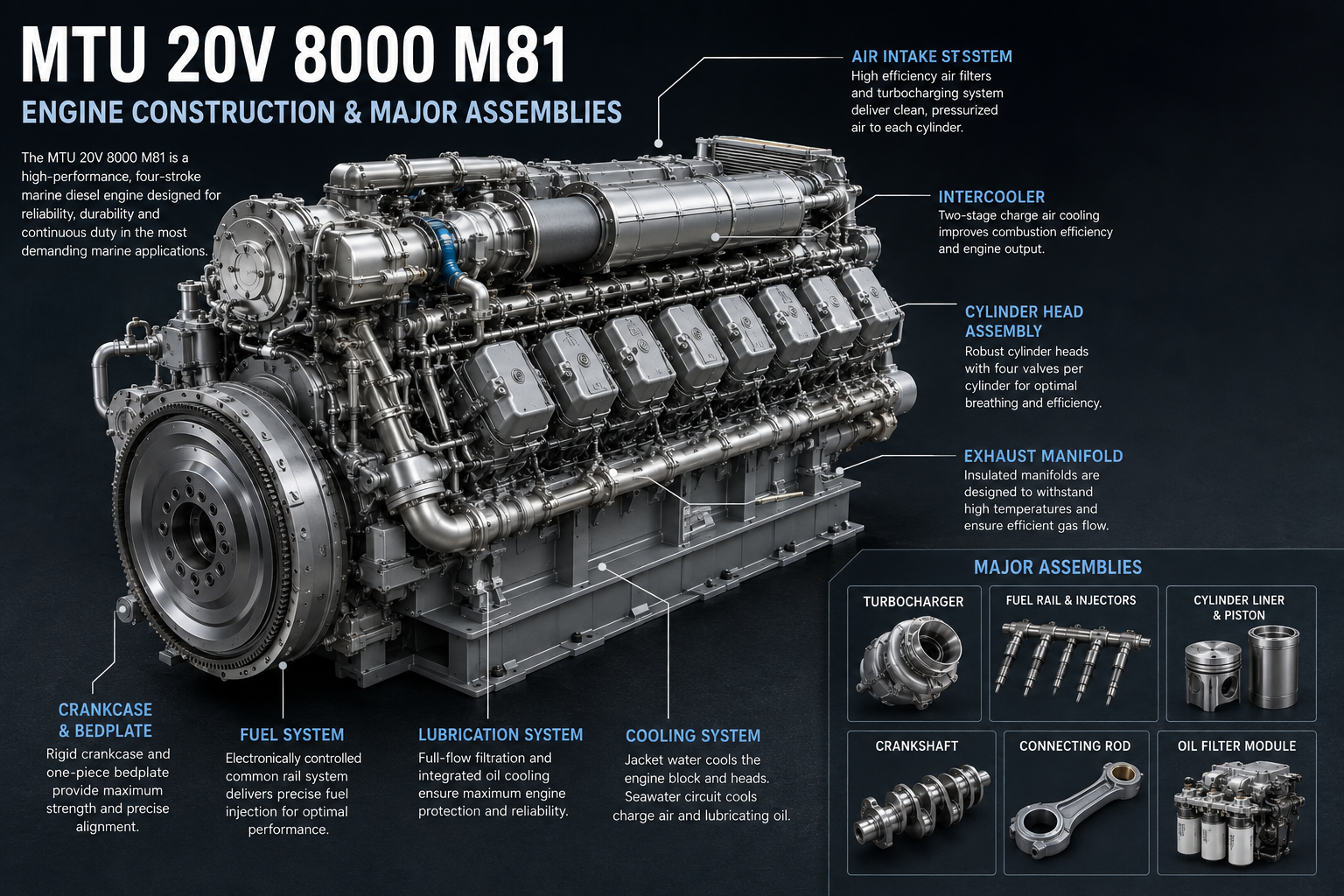
MTU 20V 8000 M81 Engine Construction and Major Assemblies: What Marine Engineers Should Inspect During Overhaul
The MTU 20V 8000 M81 belongs to the MTU Series 8000 marine engine family. It is a 20-cylinder V-engine developed for large, high-performance marine applications. Historical MTU marine-program documentation lists the 20V 8000 M81 at 8,200 kW (10,995 bhp) at 1,150 rpm, while the M81R was offered at a lower rating.
The M81 is a legacy Series 8000 variant; MTU's current product range has moved toward later M71/M71L and M91L versions. The underlying Series 8000 architecture, however, remains an excellent example of how a very large high-speed marine engine combines a rigid crankcase, individual cylinder components, a central camshaft, heavy-duty cranktrain and integrated cooling and lubrication passages. MTU documentation describes the Series 8000 around a single centrally located camshaft and a rigid engine structure designed for high firing pressures.
For an engineer, understanding these assemblies becomes particularly important when the engine is opened for inspection.
The objective should never be simply:
"Which part do we replace?"
A better question is:
"What does the condition of every major assembly tell us about how this engine has been operating?"
Where Does the MTU 20V 8000 M81 Belong?
Manufacturer: MTU
Engine family: MTU Series 8000
Engine model: MTU 20V 8000 M81
Configuration: V20 marine diesel
Rated speed: 1,150 rpm
Historical rated output: approximately 8,200 kW / 10,995 bhp
Primary subject: Engine construction and major assemblies
Historical MTU documentation lists the M81 alongside the M81R as Series 8000 propulsion engines for marine applications.
The Series 8000 itself is a very large high-speed engine platform. MTU currently describes the Series 8000 family as its high-power marine range, available in 16V and 20V configurations.
Understanding the MTU Series 8000 Engine Structure
A large marine diesel engine works because many systems share one accurately aligned mechanical structure.
The principal assemblies include:
- Cylinder block / crankcase
- Individual cylinder heads
- Cylinder liners
- Pistons and piston rings
- Connecting rods
- Crankshaft
- Main and connecting-rod bearings
- Central camshaft
- Timing gear
- Valve train
- Fuel injection equipment
- Turbochargers
- Charge-air system
- Lubrication system
- Cooling system
Series 8000 technical material specifically describes a rigid structure, a centrally located camshaft and integrated engine systems designed around the needs of a very high-output marine engine.
Cylinder Block
More Than the Frame Holding Everything Together
On an MTU 20V 8000 M81, the cylinder block or crankcase is the structural foundation of the engine.
It must maintain accurate positioning of:
- All 20 cylinders
- Crankshaft main bearings
- Cylinder liners
- Cylinder heads
- Central camshaft
- Lubrication passages
- Cooling passages
- Timing components
Series 8000 reference material describes the block as the base structure housing 20 cylinders in a V configuration, ten per bank.
This makes block condition critical.
A damaged injector can be replaced relatively easily.
A damaged crankcase changes the entire economics of an overhaul.
Structure and Support Features
The engine block must handle several different forces simultaneously.
Combustion pushes downward through the piston and connecting rod.
The crankshaft transfers that force into rotational torque.
Main-bearing saddles hold the crankshaft in position.
Cylinder heads transfer combustion forces back into the block structure.
At the same time, the block must maintain accurate:
- Cylinder geometry
- Main-bearing alignment
- Camshaft alignment
- Liner seating
- Oil distribution
- Coolant distribution
This is why an experienced overhaul team treats block measurement as a geometry problem, not simply a cleaning job.
What Should Engineers Inspect on the Cylinder Block?
Look carefully at:
- Cylinder-liner seating areas
- Main-bearing saddles
- Camshaft bearing locations
- Threaded holes
- Head-mounting areas
- Coolant passages
- Oil galleries
- Structural ribs
- External mounting points
- Evidence of fretting
- Corrosion
- Cracking
- Previous repairs
One unusual mark deserves investigation.
The question is always:
Normal service evidence—or the beginning of structural movement?
Cleaning the Cylinder Block
Cleaning should expose the condition of the metal without damaging critical surfaces.
During a professional overhaul, attention should be given to:
- Oil galleries
- Coolant passages
- Liner registers
- Bearing saddles
- Gasket faces
- Threaded holes
- Internal cavities
Old deposits can hide corrosion or cracks.
But aggressive cleaning can also destroy useful failure evidence.
Engineer's Tip
Photograph abnormal deposits, fretting and discoloration before cleaning.
Once the block is chemically cleaned or mechanically prepared, some evidence disappears forever.
Pressure Testing the Cylinder Block
Where required by the applicable MTU overhaul procedure, pressure testing can help identify leakage through:
- Coolant galleries
- Cracks
- Previously repaired areas
- Porosity
- Damaged sealing regions
The pressure, medium, temperature and test duration should come from the applicable MTU workshop documentation—not from a generic diesel-engine procedure.
MTU states that its technical documents are tailored to the specific equipment involved, making engine serial-number-specific documentation particularly important for major overhaul work.
Cylinder Block Inspection Procedures
A thorough inspection may combine several methods depending on the area being examined.
These can include:
- Visual inspection
- Dimensional measurement
- Straightness checks
- Bore alignment checks
- Surface examination
- Pressure testing
- Approved non-destructive testing
- Thread inspection
The inspection should be documented.
A useful overhaul report records both:
what was found
and
what was measured.
Guidelines for Cylinder Block Resurfacing and Repair
Don't Machine the Block Just Because a Surface Looks Imperfect
This is an important rule.
Machining removes material.
Before resurfacing any critical surface, engineers must determine:
- Is machining permitted by MTU?
- What is the original dimension?
- What material has already been removed?
- Is the surface actually distorted?
- Will machining affect liner position?
- Will it affect compression geometry?
- Will it affect cylinder-head sealing?
- Will it affect alignment with adjacent components?
A machine shop may physically be able to machine a surface.
That doesn't mean it should.
Liner Seating Areas Are Especially Important
The cylinder liner must sit correctly within the engine structure.
Inspect the liner-contact areas for:
- Fretting
- Corrosion
- Erosion
- Deposits
- Mechanical damage
- Incorrect seating
If liner positioning changes, several other engine dimensions can be affected.
Therefore liner seating must be evaluated against the correct factory dimensional specification before repair.
When Is Cylinder Block Repair Better Than Replacement?
Repair can make sense when:
- Damage is localized.
- Structural integrity remains acceptable.
- Factory repair procedures exist.
- Dimensions can remain within specification.
- Repair can be verified by measurement and testing.
Replacement becomes more attractive when:
- Structural cracking is extensive.
- Main-bearing alignment cannot be recovered.
- Severe corrosion affects critical passages.
- Multiple previous repairs exist.
- Critical dimensions are beyond repair limits.
For a Series 8000 engine, the cost of getting this decision wrong is substantial.
Cylinder Head
The MTU 20V 8000 M81 uses individual cylinder-head assemblies as part of its V20 architecture.
The cylinder head closes the combustion chamber while supporting or interfacing with:
- Intake valves
- Exhaust valves
- Valve seats
- Valve guides
- Valve springs
- Fuel injection components
- Cooling passages
- Intake passages
- Exhaust passages
The head works under repeated pressure and thermal cycling.
What Should Be Inspected on the Cylinder Head?
During overhaul, inspect:
- Combustion face
- Valve seats
- Valve guides
- Intake valves
- Exhaust valves
- Injector location
- Cooling passages
- Gasket surface
- Cracks
- Corrosion
- Deposits
- Evidence of combustion leakage
Again, comparison between cylinders is extremely useful.
On a V20 engine you have twenty combustion chambers giving you twenty opportunities for comparison.
Common Cylinder Head Issues and Troubleshooting
Different Exhaust Temperature on One Cylinder
Investigate:
- Injector
- Exhaust valve
- Intake valve
- Valve clearance
- Compression
- Cooling
- Air supply
Don't immediately condemn the cylinder head.
Coolant Loss
Possible areas to investigate include:
- Head sealing
- Cooling passages
- Gasket
- Casting condition
- Adjacent cooling system
Repeated Valve Problems
Ask whether the problem involves:
- Valve-seat geometry
- Valve guide clearance
- Combustion
- Cooling
- Incorrect adjustment
- Exhaust temperature
A new valve cannot correct the cause of repeated overheating.
Piston and Connecting Rods
The piston converts combustion pressure into mechanical force.
The connecting rod transfers that force to the crankshaft.
Together they form one of the most heavily loaded assemblies inside the engine.
During disassembly, inspect the piston for:
- Crown deposits
- Heat damage
- Ring-groove wear
- Skirt condition
- Piston-pin condition
- Evidence of scuffing
Inspect the connecting rod for:
- Big-end condition
- Small-end condition
- Alignment
- Bearing seating
- Fasteners
- Surface damage
Don't Clean the Pistons Too Quickly
Twenty pistons provide a remarkable amount of diagnostic information.
Imagine nineteen piston crowns have similar deposits.
One looks completely different.
That's not merely dirt.
That's information.
It may justify investigation of:
- Fuel injection
- Compression
- Valve sealing
- Oil consumption
- Cylinder temperature
- Air distribution
Photograph and label each piston before cleaning.
Piston Rings
Inspect:
- Compression rings
- Oil-control rings
- Ring grooves
- Ring mobility
- Wear pattern
- Carbon accumulation
A stuck ring and a worn ring are not necessarily caused by the same problem.
The failure mechanism matters.
Crankshaft and Bearings
The crankshaft is one of the most expensive and important assemblies in the MTU 20V 8000 M81.
It converts the combined power from twenty cylinders into rotational output.
The bearings support that crankshaft on a controlled lubricating-oil film.
Inspect the crankshaft for:
- Journal condition
- Scoring
- Heat discoloration
- Cracks
- Surface damage
- Dimensional changes
- Runout
- Axial condition
Main Bearings
When main bearings are removed, don't immediately discard them.
Compare all bearing shells.
Look for:
- Uneven wear
- Wiping
- Scoring
- Cavitation-like erosion
- Embedded debris
- Heat discoloration
- Edge loading
A bearing can tell you about:
- Lubrication
- Alignment
- Contamination
- Crankshaft geometry
- Loading
Connecting Rod Bearings
Apply the same approach.
If nineteen rod-bearing positions look similar and one is significantly different, investigate before simply fitting twenty new sets.
The unusual bearing may reveal the real problem.
Oil Analysis Before Overhaul
Oil-analysis history can make crankshaft and bearing inspection more meaningful.
Look at trends in:
- Iron
- Copper
- Lead
- Aluminium
- Fuel dilution
- Water
- Viscosity
- Oxidation
A rising wear-metal trend can tell the overhaul team where to pay extra attention during disassembly.
Camshaft and Timing Gear
One particularly interesting feature of the Series 8000 architecture is its single centrally located camshaft. MTU technical material highlights this centrally positioned camshaft as part of the engine's compact structural design.
The camshaft controls valve events through the engine's valve-train system.
Its relationship with the crankshaft must remain precisely timed.
Why Camshaft Timing Matters
The valves must open and close at precisely controlled points relative to piston movement.
Incorrect camshaft timing can influence:
- Cylinder filling
- Exhaust clearing
- Combustion
- Exhaust temperature
- Starting
- Power
- Engine smoothness
On an engine producing thousands of kilowatts, seemingly small timing errors can have large consequences.
Camshaft Design: Naturally Aspirated vs Turbocharged Engines
This section requires an important distinction.
The MTU 20V 8000 M81 is a turbocharged marine engine. The following comparison is therefore educational; it does not imply a naturally aspirated M81 version.
Naturally Aspirated Diesel Engine
A naturally aspirated engine depends on atmospheric pressure and piston movement to fill the cylinder.
Its cam profile and valve timing are optimized around that airflow regime.
Turbocharged Diesel Engine
A turbocharged engine supplies intake air above atmospheric pressure.
Valve timing must work together with:
- Boost pressure
- Exhaust energy
- Charge-air cooling
- Cylinder filling
- Exhaust scavenging
Series 8000 engines use turbocharging and charge-air systems as central parts of their high-output design.
Therefore a camshaft should never be substituted simply because another shaft physically fits.
Cam profile and timing belong to the engine's combustion design.
Timing Gear Alignment
Timing gears establish the mechanical relationship between:
- Crankshaft
- Camshaft
- Associated drive systems
Alignment marks and factory positioning procedures are critical.
A related MTU workshop manual demonstrates the general MTU principle clearly: camshaft installation requires the specified gear markings to match at the camshaft/crankshaft gear mesh.
For the Series 8000 M81, however, the specific M81 workshop manual and engine serial number must govern the procedure.
Do not transfer timing marks, torque values or clearances from a Series 2000 or Series 4000 manual.
Before Removing the Camshaft
Document:
- Timing positions
- Gear markings
- Bearing positions
- End-float condition
- Lobe condition
- Gear backlash where applicable
- Existing wear patterns
Mark components carefully.
A photograph before disassembly can save significant troubleshooting later.
Camshaft Bearing Replacement
Camshaft bearings maintain accurate shaft support throughout the engine.
During inspection, check:
- Bearing surface
- Oil supply
- Journal condition
- Alignment
- Clearance
- Evidence of overheating
- Edge wear
Bearing replacement is not simply a matter of driving the old bearing out and installing another.
The replacement must maintain:
- Correct position
- Correct oil-hole alignment
- Correct installed geometry
- Correct running clearance
Timing Gear Alignment After Bearing Work
After camshaft-bearing replacement, verify that the camshaft rotates correctly and that the timing drive remains aligned.
A bearing installed slightly incorrectly can cause:
- Restricted oil supply
- Tight rotation
- Uneven camshaft loading
- Gear misalignment
- Accelerated wear
So don't judge successful installation merely by:
"The bearing went in."
The important question is:
"Is the complete camshaft system correctly aligned after installation?"
Techniques for Machining Camshaft Bearings
This Is Precision Machine Work—not General Workshop Boring
There are cases on some engine designs where camshaft bearing bores or installed bearing elements require precision finishing.
However, on an MTU Series 8000, machining should only be performed where the applicable MTU repair instruction explicitly permits it.
The general engineering principles are:
- Establish the engine's approved reference datum.
- Measure the complete camshaft tunnel before removing material.
- Determine whether distortion is local or extends through several positions.
- Check bearing-bore alignment.
- Install or machine only according to the specified repair method.
- Maintain oil-hole orientation.
- Control final diameter and surface finish.
- Verify alignment through the complete camshaft axis.
- Clean all oil passages after machining.
- Re-measure before final camshaft installation.
Actual bore sizes, allowable material removal, concentricity limits and machining-tool dimensions must come from the applicable MTU 20V 8000 M81 workshop documentation. MTU emphasizes equipment-specific technical documentation for precisely this reason.
Why Line Alignment Matters More Than One Perfect Bearing
Imagine one camshaft bearing bore is machined perfectly to diameter.
But it sits slightly off-center relative to the remaining bearings.
The individual bore might measure correctly.
The camshaft system can still be wrong.
That's why long-shaft bearing work should be thought of as an alignment problem, not simply a diameter problem.
Never Leave Machining Debris Behind
After bearing or block machining, oil galleries and internal passages require meticulous cleaning.
Even microscopic metallic particles can later reach:
- Camshaft bearings
- Main bearings
- Connecting-rod bearings
- Turbocharger lubrication
- Other precision surfaces
Machining quality means nothing if swarf remains inside the engine.
Real Marine Overhaul Scenario
Imagine an MTU 20V 8000 M81 entering a scheduled major overhaul.
The engine has operated reliably, but historical data shows:
- Slowly increasing wear metals
- Minor cylinder-to-cylinder temperature differences
- Slight changes in oil consumption
During disassembly, engineers find:
- Nineteen pistons showing similar deposits
- One piston with noticeably different combustion deposits
- One connecting-rod bearing with abnormal edge wear
- Minor fretting at one liner seat
- Several camshaft bearings showing uneven wear
Instead of treating each issue separately, the engineering team asks whether they are connected.
The unusual piston leads to injector and valve inspection.
The rod-bearing pattern triggers crankshaft measurement.
The liner-seat condition leads to block inspection.
The camshaft-bearing wear leads to alignment checks.
Now the overhaul is doing what it should do:
finding relationships between symptoms.
Engineer's Toolbox
During a major MTU 20V 8000 M81 Engine Construction inspection, document:
- Cylinder block condition
- Liner seating
- Cylinder-head condition
- Piston deposits
- Piston rings
- Connecting rods
- Rod bearings
- Main bearings
- Crankshaft journals
- Crankshaft alignment
- Camshaft lobes
- Camshaft bearings
- Timing gears
- Oil passages
- Cooling passages
- Injector condition
- Valve condition
Use cylinder and bearing-position numbers in photographs and reports.
Marine Engineer Tip
Measure before machining. Photograph before cleaning. Compare before replacing.
Those three habits can turn a normal overhaul into a valuable diagnostic inspection.
Common Overhaul Mistakes
Avoid:
- Cleaning components before documenting abnormal deposits.
- Mixing pistons or connecting rods between cylinders.
- Discarding old bearings before studying their wear.
- Resurfacing the block without dimensional verification.
- Assuming a crack is only superficial.
- Machining camshaft bearing bores without approved limits.
- Failing to align bearing oil holes.
- Installing timing gears without verifying marks.
- Ignoring abnormal wear on only one cylinder.
- Using workshop data from another MTU engine family.
Frequently Asked Questions
Is the MTU 20V 8000 M81 part of the MTU Series 8000?
Yes. Historical MTU documentation lists the 20V 8000 M81 and M81R as Series 8000 marine propulsion engines.
How much power does the MTU 20V 8000 M81 produce?
Historical MTU sales-program documentation lists the M81 at approximately 8,200 kW / 10,995 bhp at 1,150 rpm.
Does the MTU Series 8000 have one or two camshafts?
Series 8000 technical material describes a single centrally located camshaft.
Is the MTU 20V 8000 M81 naturally aspirated?
No. The Series 8000 uses turbocharging and charge-air systems to achieve its high power density. Discussion of naturally aspirated camshaft design is useful as an engineering comparison, but it does not describe the M81 configuration.
Can an MTU 8000 cylinder block be resurfaced?
Possibly in specific repair situations, but only within the dimensional and procedural limits given in the applicable MTU repair documentation. Large structural components should not be generically resurfaced without determining the effect on liner seating, head geometry and engine alignment.
Can camshaft bearings be machined?
Only when the applicable MTU repair procedure permits it. Bearing bore alignment, oil-hole orientation, final clearance and camshaft-axis geometry are critical.
Should timing marks be recorded before disassembly?
Yes. Document timing positions and gear relationships before removing components, then follow the Series 8000-specific workshop instructions during assembly.
Related MTU Series 8000 Parts
Major overhaul components may include:
- Cylinder blocks / crankcases
- Cylinder heads
- Cylinder liners
- Pistons
- Piston rings
- Connecting rods
- Connecting-rod bearings
- Main bearings
- Crankshafts
- Camshafts
- Camshaft bearings
- Timing gears
- Valves
- Valve guides
- Gaskets
- O-rings
- Oil pumps
- Water pumps
- Turbocharger components
- Fuel-system components
Part numbers should be confirmed using the engine serial number and applicable MTU BOM.
Explore MTU Series 8000 Marine Engines
The MTU 20V 8000 M81 belongs to the MTU Series 8000 family, alongside other historical and later Series 8000 marine-engine variants.
Explore MTU Marine Engines & Spare Parts
Related Engine Pages
- MTU 20V 8000 M81 Marine Engine Spare Parts
- MTU 20V 8000 M81R Marine Engine Spare Parts
- MTU 20V 8000 M71 Marine Engine Spare Parts
- MTU 20V 8000 M71L Marine Engine Spare Parts
- MTU 20V 8000 M91L Marine Engine Spare Parts
- MTU Series 8000 Marine Engine Spare Parts
Worldwide MTU Marine Spare Parts Supply
Alfa Marine Spare Parts supports shipyards, ship repairers, marine engineers, chief engineers, technical superintendents, fleet operators, offshore operators, government fleets, maritime contractors, marine service companies and marine equipment distributors.
We help customers source components for MTU Series 8000 maintenance and major overhaul projects, including engine internals, bearings, cylinder components, timing components, cooling parts and lubrication-system parts.
Browse Our Complete Catalog
For MTU 20V 8000 M81 components, provide as much identification as possible:
Engine model + serial number + existing part number + component position + quantity + photographs where available.
Browse MTU Marine Engines & Spare Parts
Why Choose Alfa Marine Spare Parts?
A major Series 8000 component shouldn't be ordered simply from the description:
"Need MTU 8000 camshaft."
The M81 is a specific Series 8000 configuration, and major components should be confirmed against engine identification and applicable BOM data.
Alfa Marine Spare Parts can assist with sourcing genuine, OEM, aftermarket, remanufactured and reconditioned MTU marine engine components, depending on application and availability.
For cylinder heads, crankshafts, bearings, pistons, camshafts or other major assemblies, accurate identification before international shipping helps reduce expensive ordering errors.
Contact Alfa Marine Spare Parts
Email: request@alfamarinespareparts.com
MTU Marine Engines & Spare Parts
Contact Alfa Marine Spare Parts for MTU 20V 8000 M81 cylinder heads, pistons, connecting rods, crankshafts, bearings, camshafts, timing components and other Series 8000 marine engine spare parts.
One Final Thought
Understanding MTU 20V 8000 M81 Engine Construction isn't simply about learning the names of major components.
The cylinder block provides the geometry.
The cylinder heads control combustion sealing and gas exchange.
The pistons and connecting rods transmit combustion force.
The crankshaft converts that force into propulsion power.
The bearings preserve alignment through an oil film.
And the centrally located camshaft and timing system ensure that all twenty cylinders breathe at precisely the correct moment.
During an overhaul, every one of those assemblies becomes evidence.
A worn bearing tells a story.
A different piston deposit tells a story.
A fretted liner seat tells a story.
An uneven camshaft bearing tells a story.
The engineer's job isn't simply to replace what looks worn.
It is to understand why it wore that way—and correct the cause before the MTU Series 8000 returns to sea.